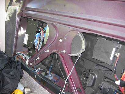
· Not sure if you’ll find this useful or not, but I wanted to know the path of the factory speaker wires, so I took the time to figure it out. They run down from the radio, under the carpet, across the hump and to the right of the car, just in front of the passenger seat mounting points. They enter the right side wiring duct. The front right pair run forward to door, the remaining 3 pair run back. The front left pair then break off at the rear seat mounting point and run left and to the front door. The two remaining pair continue in the wiring duct to the rear speakers.
· The remote gain cable for the Infinity sub is a “crossed” configuration in case you want to put a new connector on. Look at both ends and make sure the colors are in the opposite order when looking at the same side of the plug.
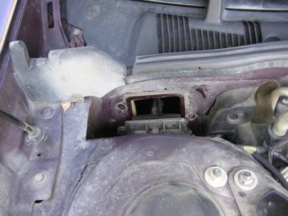
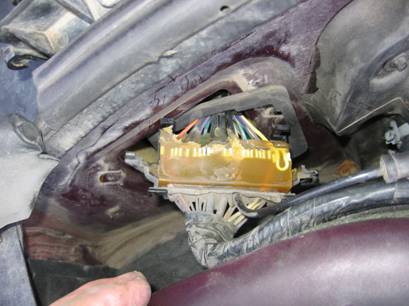
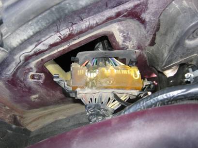
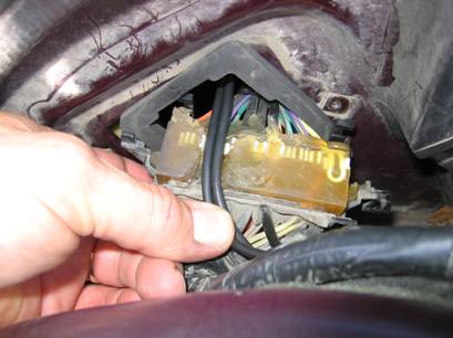
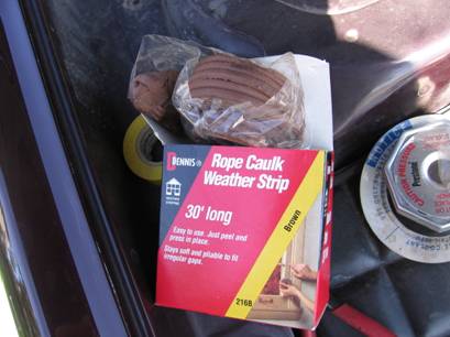
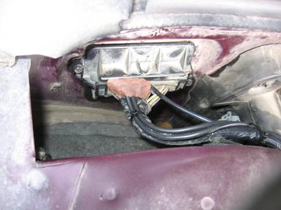
· There is a firewall cable pass through that has enough space to add wires. It’s located on the right side of the car, behind the strut tower. Take it apart, dig out some of the compound, run your wires, seal it back up with plumber’s putty, reassemble. I ran two 12 gauge power wires through this.
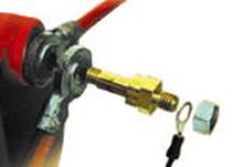
· I installed a battery terminal power tap extension to supply power to a new fuse holder. You will need an “Extended Length” adapter (about 2” total length). The short ones won’t work because there are two cables on the battery. I then ran 2- 12 gauge wires to a 30 amp fuse holder. One supplies power to the sub, the other power to the radio and a couple of new cigarette lighter sockets that I’m putting in the front ashtray. I’m sick of losing power to my cell phone, GPS or laptop when the car is turned off.
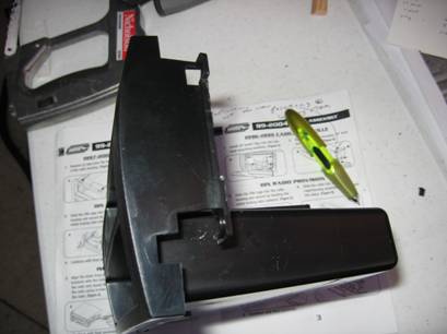
· The instructions for the radio adapter housing were not very good. This is the plastic device that you need to mount your new radio into the OEM radio dash hole. Here’s what it should look like when you have cut off the correct pieces.
· Front door issues - If you have a 6 speaker system, one that has tweeters in the front door panels, I recommend that you get a component speaker set for the front. This will come with passive crossovers that you can mount inside the door panel. You will need a little creativity to mount the new tweeters. I don’t have pictures of my tweeter/crossover installation (sorry). I was in too much of a hurry. I’ll do my best to describe this part.
§ Remove the old tweeters. Cut the tweeter out of the plastic mount, leaving a hole.
§ I siliconed my new tweeter to the inboard side of the plastic mount. I had to drill a hole along the edge of old tweeter hole to get the wires through. I used several small washers between the plastic mount and the door panel screw holes so my new tweeter didn’t touch the speaker grill on the door panel.
§ The crossover was mounted to the inside the door panel. There is plenty of space for it to the rear, under the arm rest. I cut out some of the insulation and siliconed a piece of ½” plywood to the door panel. I then used a large piece of Velcro to fasten the crossover to the plywood. I put the plywood in because the door panel didn’t provide a flat enough area for mounting. You can use screw instead of the Velcro if you wish. I used Velcro so that removal would be easier. My crossovers had a unique cover that would be tough to remove if the base were screwed down. I could have left the cover off, but the compulsive part of me wouldn’t permit it.
· The woofers in these component speaker kits won’t have a tweeter cone. This is good because tweeter cones may protrude too far and require the cutting of the door panel and use of the grills. This is not desirable if you want to keep the factory look. There isn’t much clearance between the speaker and the panel. I think you’ll be happier with something like what I used, the Polk DB5250.
· I put Polk DB690 5x7’s in the back. Some home installers are using 3M “Mounting Tape”, part number 110 to hold the rear speakers in. They like this method because you don’t have to drill. I’m not sure that this is a good idea however. If you get in a serious accident, those things could become deadly missiles. On the other hand, the rear deck upholstery panel might keep them contained. If you decide to drill, get a General brand 90 degree drill accessory.
· Misc. Pics.
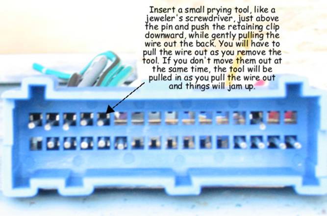
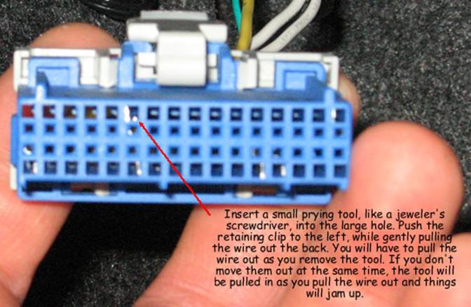
o Scosche Connector Pin Removal
· The OEM front left speaker was moved to behind the rear seat back to provide my chime that will come from the relocated OEM radio. After installing the seats, the chime is very muted. I decided at the end of the project to run a two-pair wire from this speaker to the front ashtray. I spliced this wire into one of the speaker wires and will install a small switch in the ashtray. This will allow me to disable the chime when I want the radio playing with the doors open.
· Removing the front carpet retainers (plastic door sill) - Start at the rear and use a upholstery removal tool and pry the fasteners out of their holes. When you have them loose, pull down on the front vertical part and it will slide out. It releases with a fair amount of difficulty. If you wish to remove the door pillar trim, first remove the rear carpet retainer. Reinstall door pillar trim, rear carpet retainer, then front carpet retainer.
· The Scosche connectors were purchased from audiooutfitter.com. Price was very good.
· Getting the trim off from around the OEM radio was a bit tricky. I took a couple of pictures of this item after removal and you’ll find them in the compressed file mentioned at the end of this document. This should give you a good idea of what you’re working with. You basically have to pry the trim panel out. Start by opening the glove compartment and pry it with a screwdriver.
· The antenna adapter supplied by Crutchfield stuck out too far and was hitting the air plenum in the dash cavity. There is precious little room in this area for an aftermarket radio, but it can be done. However, it was impossible to install the radio with this extra inch or two of antenna adapter sticking out. I had to use my dremel tool to cut away the 90 degree metal strain relief. After removal I put JB Weld on the connector to act as a strain relief.
Infinity BassLink Subwoofer Wiring Information
An AMP Mate-n-Lock 3-position
connector is installed on wires 4, 5 and 6 with a corresponding connector on
the wiring.
I installed blind
nuts on the spare tire cover and fastened the sub to a ¾” piece of plywood. I
put together a couple of thumb screws and use them to hold the plywood to the
blind nuts. This allows easy removal of the sub if I want the luggage space.
It’s a little wobbly, but secure. I’ll see how it will work out and design
something else if necessary. Sometime Later…
this is going to be fine. Pictures of it can be found in the compressed file
mentioned at the end of this document.
|
# |
Subwoofer Terminals |
Cable Source/Type |
Routing Path |
Destination |
|
|
|
|
|
|
|
1 |
RCA Jack, Front right |
cablesforless.com, 12
Foot Stereo Python Cable, $6.99 |
From trunk, under rear
seat, down center of vehicle, along the right side of hump. |
Radio subwoofer out
connectors |
|
2 |
RCA Jack, Front left |
As above |
As above |
As above |
|
3 |
Remote Gain Control, RJ11 port. |
Factory supplied, 4 wire
modular phone cable, black, RJ11 connectors, crossed configuration. |
As above |
Remote gain potentiometer
located in front ashtray |
|
4 |
Ground |
Belden 8918, green/yellow |
As above, but only to
grounding point |
Ground point behind rear
seatback |
|
5 |
Rem |
Belden 8918, blue |
From trunk, under rear
seat, down center of vehicle, along the right side of hump. |
Radio, External Amplifier
Control Power Lead |
|
6 |
Battery, 20 amp |
Belden 9912, black |
Wiring duct along right
side of car and through firewall pass through. |
Connects to aftermarket
Buss 30 amp fuse in engine compartment |
Panasonic CQ-C8803U
Head Unit
1AMP
Mate-n-Lock 3-position connector is installed on wires 1, 2 and 3 with a
corresponding connector on the wiring.
2
AMP Mate-n-Lock 2-position connector is installed on wires 4 and 5 with a corresponding connector on the
wiring.
3
AMP Mate-n-Lock 8-position connector is installed on wires 6-13 with a corresponding connector on the
wiring.
4 The
power window circuit is part of the Cadillac “Retained Accessory Power” (RAP)
feature. By using this circuit for the Acc/Ign power (red) on the new radio, I
will benefit from the delayed (10 minute) power off on this circuit. The power
will turn off after 10 minutes or when a door is opened, whichever is first.
This circuit is on a 12 AWG orange wire and can be found throughout the car. I
tapped into it inside the right wire duct because I was in there anyway. You
may find it easier to connect to it inside the right or left front kick panels.
|
# |
Radio Connectors/Wires |
Cable Source/Type |
Routing Path |
Destination |
|
|
|
|
|
|
|
1 |
1Switched
power, acc or ignition, red |
1Common 18 AWG hookup wire, red. (Didn’t have red
Belden) |
Down from radio opening,
across and under dashboard to right
kick panel and into right wire duct |
4Power window circuit, orange wire, 12 AWG. |
|
2 |
1Constant
battery power, yellow |
1Belden 8918, yellow |
Down from radio to inline
fuse |
Spliced into the black
Belden 9912 via a 15 amp inline fuse. |
|
3 |
1Ground, black |
1Belden 8918, green/yellow |
Down from radio opening,
across and under dashboard to right
kick panel |
Fastened to factory
ground screw. |
|
4 |
2Power
antenna, blue |
2Not applicable |
Local connection |
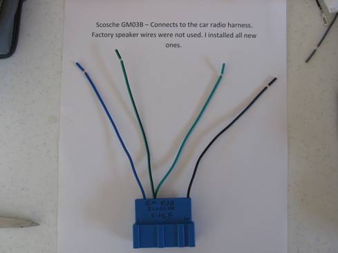
Pin F3 on Scosche GM03B
connector and then to the OEM radio harness |
|
# |
Radio Connectors/Wires |
Cable Source/Type |
Routing Path |
Destination |
|||||
|
|
|
|
|
|
|||||
|
5 |
2External
Amplifier Control, blue/white |
2Belden 8918, blue, |
From radio opening, down to
hump then along the right side of hump, under rear seat, to trunk |
Rem terminal on sub via
AMP Mate-n-Lock connector |
|||||
|
6 |
Front left speaker, +, white |
Phillips speaker wire,
clear, 16 AWG |
Across and under dash to
left door |
Line in on Polk component
crossover installed in door panel |
|||||
|
7 |
Front left speaker, -, white/black |
Same as above except
clear with stripe |
Same as above |
Same as above |
|||||
|
8 |
Front right speaker, +, gray |
Same as item 6 |
Across and under dash to
right door |
Same as above |
|||||
|
9 |
Front right speaker, -, gray/black |
Same as above except
clear with stripe |
Same as above |
Same as above |
|||||
|
10 |
Rear left speaker, +, green |
Same as item 6 |
From radio opening, down
to hump then along the right side of hump, under rear seat, to trunk |
To + terminal on Rear
right speaker |
|||||
|
11 |
Rear left speaker, -, green/black |
Same as above except
clear with stripe |
Same as above |
To - terminal on Rear
right speaker |
|||||
|
12 |
Rear right speaker, +, violet |
Same as item 6 |
Same as above |
To + terminal on rear
left speaker |
|||||
|
13 |
Rear right speaker, -, violet/black |
Same as above except
clear with stripe |
Same as above |
To - terminal on rear
left speaker |
|||||
|
14 |
DC to DC converter bundle |
Factory supplied with
connector |
Local |
To DC converter box to
the right of radio on dash frame |
|||||
|
# |
Radio Connectors/Wires |
Cable Source/Type |
Routing Path |
Destination |
|||||
|
|
|
|
|
|
|||||
|
15 |
Auxiliary in, RCA, right, red |
Manufactured RCA
extension cable |
Down to ashtray |
Male stereo plug will
remain in ashtray |
|||||
|
16 |
Auxiliary in, RCA, left, white |
Manufactured RCA
extension cable |
Down to ashtray |
Male stereo plug will
remain in ashtray |
|||||
|
17 |
Subwoofer out, RCA, right, red |
Manufactured RCA
extension cable, cablesforless.com, 12 Foot Stereo Python Cable, $6.99 |
From radio opening, down
to hump then along the right side of hump, under rear seat, to trunk |
Sub, RCA Jack, Front
right |
|||||
|
18 |
Subwoofer out, RCA, left, white |
Manufactured RCA
extension cable, cablesforless.com, 12 Foot Stereo Python Cable, $6.99 |
From radio opening, down
to hump then along the right side of hump, under rear seat, to trunk |
RCA Jack, Front left |
|||||
|
19 |
Antenna, black |
Coaxial with adapter |
To factory harness |
Antenna, keep as far away
from RCA cables as possible to avoid signal cross over. |
|||||
|
20 |
Preamp outputs |
Not used |
Not used |
Not used |
|||||
Factory Radio Harness
1Connections
not shown under the “Harness
Pin Number and wire color” column are not used by the GM radio harness.
All unused pins in
the Scosche connectors were removed. I moved the green and green/black speaker
pair to E and F6 for the data circuit. Here’s how to
remove the pins.
2 I did
not want a floating ground on the relocated OEM radio, so I ran the same ground
from the radio harness to the radio. Reason: To reduce variables associated
with the data line extension/relocation. If the chime function doesn’t work (it
did), I’ll know it’s not likely due to unusual grounding.
|
# |
1Harness Pin Number and wire color |
Function |
Routing Path |
Destination |
|
|
|
|
|
|
|
1 |
F1, orange |
12 v power |
Not used |
Not used |
|
2 |
F3, dark green |
Antenna power relay |
Local, connects to Scosche GM03B, then a 2
position AMP Mate-n-Lock |
Blue wire on radio |
|
3 |
F4, orange/black |
16 volt reference for
dimming circuit |
Not used |
Not used |
|
4 |
F5, black |
Dimming circuit ground |
Not used |
Not Used |
|
5 |
F6, purple |
Data |
Connects to GM03B pin F6,
then out on a green/ black wire to a gray wire. The gray wire goes down to
hump then along the right side of hump, under rear seat, to trunk |
Scosche GM03RB, pin F6,
green/black wire and relocated OEM radio in spare tire cavity |
|
6 |
F12, tan |
Front left speaker, + |
Not used |
Not used |
|
7 |
F13, gray |
Front left speaker, - |
Not used |
Not used |
|
# |
1Harness Pin Number and wire color |
Function |
Routing Path |
Destination |
|
|
|
|
|
|
|
8 |
F14, light blue |
Rear right speaker, - |
Not used |
Not used |
|
9 |
F15, dark blue |
Rear right speaker, + |
Not used |
Not used |
|
10 |
E5, gray |
Interior lamps, dimming |
Not used |
Not used |
|
11 |
E6, purple |
Data |
Connects to GM03B pin E6,
then out on a green wire to a white wire. The white wire goes down to hump
then along the right side of hump, under rear seat, to trunk |
Scosche GM03RB, pin E6,
green wire and relocated OEM radio in spare tire cavity |
|
12 |
E7, light blue |
Cell phone |
Not used |
Not used |
|
13 |
E8, dark blue |
Cell phone |
Not used |
Not used |
|
14 |
E12, brown |
Rear left speaker, + |
Not used |
Not used |
|
15 |
E13, yellow |
Rear left speaker, - |
Not used |
Not used |
|
16 |
E14, dark green |
Front right speaker, - |
Not used |
Not used |
|
17 |
E15, light green |
Front right speaker, + |
Not used |
Not used |
|
18 |
E16, black |
Ground2 |
Connects to GM03B pin
E16, then out on a black wire to a green/yellow wire. The green/yellow wire
goes down to hump then along the right side of hump, under rear seat, to
trunk |
Scosche GM03RB, pin E16,
black wire and relocated OEM radio in spare tire cavity |
OEM Delco Radio,
relocated to spare tire cavity in trunk
I relocated the radio
to the trunk for a couple of reasons. a). I wanted to
retain the chime function. To me, it’s not just an annoying sound. It’s the way
the car gets my attention when something requires it. b). some Cadillac owners
who installed new head units AND removed the OEM radios were having problems
with their security systems and remote entry key fobs (cars were going into a
special low power mode and shutting down everything). I didn’t want to take any
chances considering the scope of this project. The computer in Cadillacs
communicates with the radio. All chimes are generated by the radio on command
of the computer. The data lines on E and
F6 communicate to the radio, “Please send this kind of chime” and the radio
responds by sending the chime to the Front left speaker. My particular year may
not have the level of integration of later years and I might have been OK by
just removing the radio. An interesting point that I will mention: the IRC
codes that get set are related to the radio communications system. Some folks
got IRC codes set when they removed their radio. I did not get codes which sort
of reinforces the thought that my model year is not as integrated.
|
# |
Radio Pin numbers |
Function |
Routing Path |
Destination |
|
|
|
|
|
|
|
1 |
F1 |
Power |
Yellow 18 AWG wire goes
around left side of trunk to fuse panel on the left, behind the rear seat
back |
I spliced it into the
orange radio fuse wire that comes off the 10 amp radio fuse. |
|
2 |
F6 |
Data |
Connects to GM03RB pin
F6, then out on a green/ black wire to a gray wire. The gray wire goes around
left side of trunk, to the front center of the trunk , then under rear seat,
along the right side of hump, up into radio hole in dash |
GM03B, pin F6 located in
front dash |
|
3 |
F12 |
Front left speaker, + |
Connects to GM03RB pin
F12, then out on a white wire around left side of trunk. |
Positive terminal on one
of the old front door speakers that I mounted behind the rear seat back. |
|
4 |
F13 |
Front left speaker, - |
Connects to GM03RB pin
F13, then out on a white/black wire around left side of trunk. |
Negative terminal on one
of the old front door speakers that I mounted behind the rear seat back. |
|
|
|
|
|
|
|
# |
Radio Pin numbers |
Function |
Routing Path |
Destination |
|
|
|
|
|
|
|
5 |
E6 |
Data |
Connects to GM03RB pin
E6, then out on a green wire to a white wire. The white wire goes around left
side of trunk , to the front center of the trunk , then under rear seat, along the right side
of hump, up into radio hole in dash |
GM03B, pin E6 located in
front dash |
|
6 |
E16 |
Ground |
Connects to GM03RB pin
E16, then out on a black wire to a green/yellow wire. The green/yellow wire
goes around left side of trunk , to the front center of the trunk , then under rear seat, along the right side
of hump, up into radio hole in dash |
E16 on radio harness in
front dash |
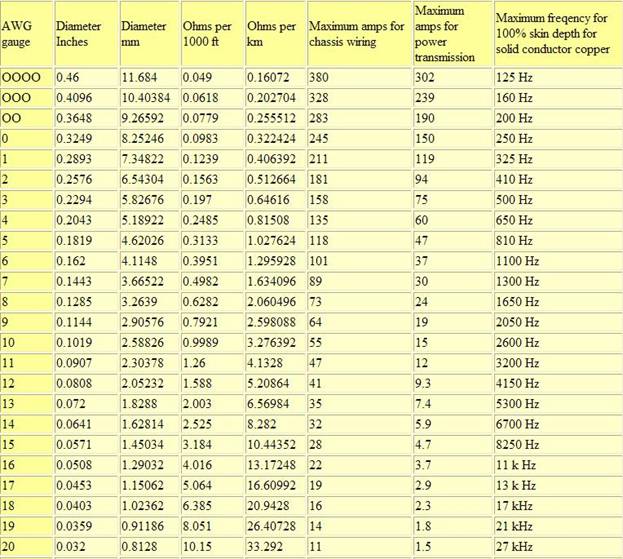
Following provided by http://www.powerstream.com/Wire_Size.htm
Load Carrying Capacities
The following chart is a guideline of ampacity or copper wire current carrying capacity following the Handbook of Electronic Tables and Formulas for American Wire Gauge. As you might guess, the rated ampacities are just a rule of thumb. In careful engineering the insulation temperature limit, thickness, thermal conductivity, and air convection and temperature should all be taken into account. The Maximum Amps for Power Transmission uses the 700 circular mils per amp rule, which is very very conservative. The Maximum Amps for Chassis Wiring is also a conservative rating, but is meant for wiring in air, and not in a bundle. For short lengths of wire, such as is used in battery packs you should trade off the resistance and load with size, weight, and flexibility.
Removing pins from the Scosche connectors:
o This doesn’t require a lot of force. Use a gently sustained push on the correct spot while pulling the wire out. You’ll need to remove the gray plastic retainers from the GM03RB connector before you can remove the pins.
1. Remove the plastic covers from the door pull handle. Pry from the outside edges (front and rear).

2. Remove the plastic panel from behind the handle used to open the door. Pry the rear side out gently.
3. Remove the #1 Philips screws from the pull handle.
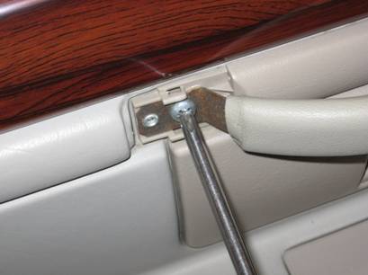
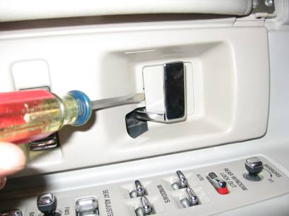
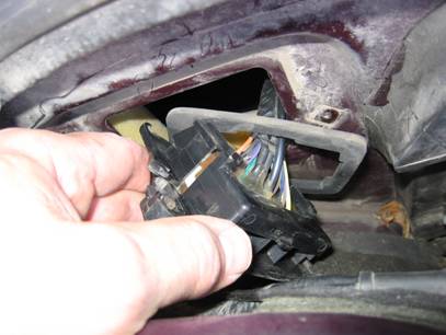
4. We’re going to remove the panel containing the door lock switch. Wiggle the panel around a bit until it comes off the door handle. Remove the connector shown below. This connector provides power to the illumination lamp above the door lock switch.
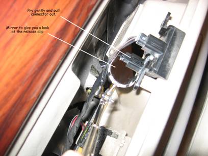
5. Release the clip on the door lock switch and remove.
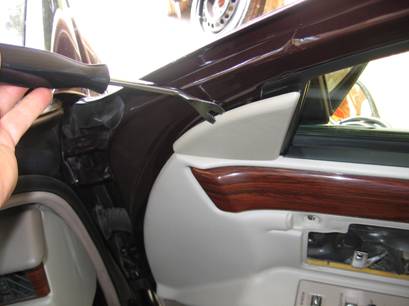
6. Use an upholstery removal tool and release the triangle shaped piece of plastic that covers the mirror bolts.
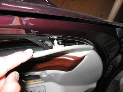
7. Wiggle the door panel upward until the “legs” disengage from the door. Lean the top in, put the bottom legs back into their holes and start removing the connectors. Remove the following.
· Tweeter connector
· White courtesy light connector
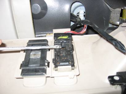
· Depress the metal clips on the seat switch panel and pull up. Then disconnect everything there.
· Remove the door panel completely and store

A too short battery power tap. You’ll need one about 2” long. Try your local stereo installation shop.
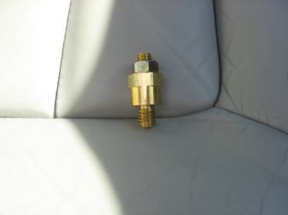
This is the one you need.
Chime speaker
Here are all the pictures I took in a compressed file. It’s 88 meg.